The Turbo:FlangesHow To Read A Compressor MapHow To Calculate A/RHow to Calculate TrimWhat Is Compressor SurgeBearing TypesFlanges:The most commonly available flanges are T3, T4 and T6, though there are many, many custom flanges out there on OEM and specific use turbos. Most aftermarket turbos will use one of the below flanges, though there is a movement toward V-Band style flanges currently. Flange size of the turbo is generally dictated by the size of the exhaust housing, which is, in turn, dictated by the turbine wheel. Some turbos are available in multiple flange sizes with no other changes. As a general rule, if a larger flange is available for your
properly sized turbo, and you can fit it, bigger is better.
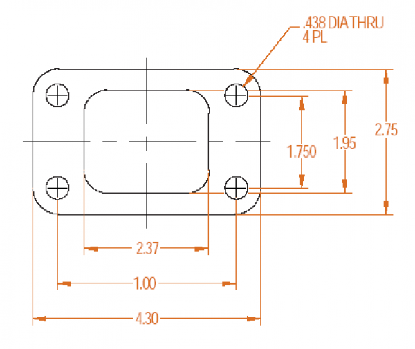
T3:
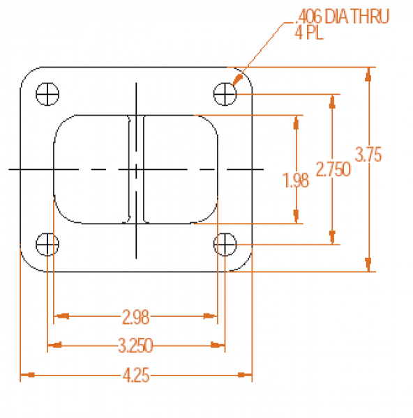
T4:
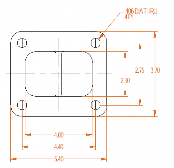
T6:
 How To Read A Compressor Map:
By Jacob Isaac-Lowry
We?ll start by looking at a sample flow map.
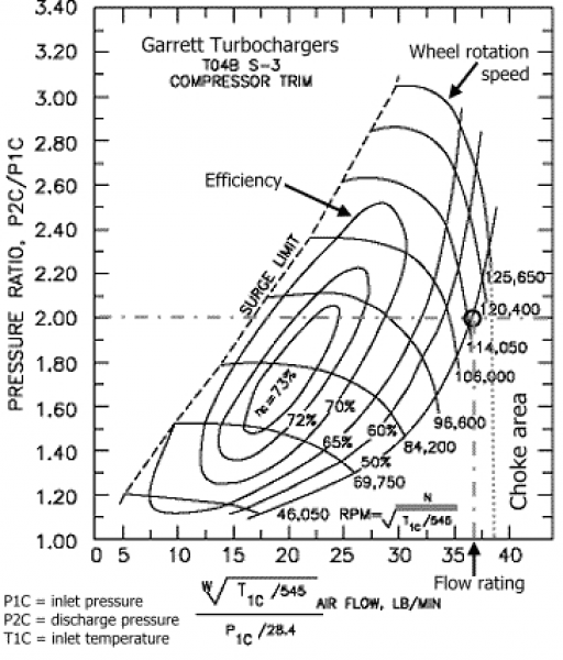
From the top of the chart we can see that this is a Garret TO4B turbo with and S-3 compressor wheel.
Understanding the Axis:1. First we will start by looking at air flow through the turbo measured on the x-axis. Garrett uses lb/min on their maps while other companies like Mitsubishi use cubic feet per minute (cfm). Since I think it?s easier to work with cfm, we?ll convert. Every 10 lb/min is equal to 144.72 cfm, remember this.
2. The pressure ratio measured on the y-axis is merely the ratio of air pressure leaving to the turbo to air pressure entering the turbo. Since atmospheric pressure at sea level is 14.7 psi, if you were to run 29.4 psi of boost, the pressure ratio would be 2.
Understanding Information within the Map:1. The oblong ovals on the chart or ?islands? as they are called represent the efficiency of the turbo in that range. As you can see on this map, the most efficient operation (73%) is in the very center of the chart. This is general characteristic of most turbochargers. Without getting into the thermodynamics of adiabatic heat-pumps, we?ll just say that efficiency is a measure of how much excess heat the turbo puts into the compressed air coming out of the outlet. So intuitively, more efficient is better.
2. Wheel rotational speed is simply the rpm at which the compressor wheel is spinning.
3. The choke point, which is usually not indicated on flow maps, is the maximum flow rating the turbo is capable of regardless of pressure or efficiency.
4. Beyond the surge limit on the left of the plot, compressor surge occurs. In layman?s terms, this phenomenon is caused by a back pressure wave entering the exit of the compressor housing and disrupting flow through the compressor wheel. Surge will kill turbos and is to be avoided at all costs.
Calculating your Engine?s Flow RequirementsNow that you can read and understand a compressor flow map, its time to figure out how to match a turbo to your engine, this involves selecting the proper compressor and turbine wheels along with the right combination of housing A/R. A mismatched turbo could not only result is extreme lag, but also wasted potential as a turbo can easily outflow an engine. I.e. bigger is not always better.
The only real calculation that needs to be done is to determine how much air you engine is actually flowing. This depends on a number of things including the RPM, absolute temperature (Rankin, equal to 460 + Fahrenheit temp), absolute manifold pressure (psi, equal to boost pressure plus atmospheric pressure), and lastly the engine volumetric flow or EVF in cfm.
First to calculate EVF use the following equation:

Next we?ll use EVF to calculate the amount of air in lb/min the engine is flowing under boost and at temperature using this equation:
 Where N is the airflow in lb/min, P is the absolute pressure in psi, and T is the absolute ambient temperature in Rankin.
 Finally, multiply N by the volumetric efficiency of your engine (VE). This compensates for the fact that upon every cycle of the engine, not all of the old air/fuel mix in the cylinders is forced out the exhaust. Thus there is a difference between the actual airflow through and engine and the predicted airflow. This discrepancy is equated to a VE. There is literally thousands of hours worth of online reading about volumetric efficiencies for just about every production engine. To get the most accurate results from this step I would suggest researching your engine and coming up with the most realistic VE possible as this does have a significant affect on engine flow. If you are just messing around with compressor flow maps and need a value for VE just to experiment with, 85% efficiency is a nice conservative number for most modified turbocharged cars at high rpm (6500-7500). Keep in mind though that on a forced induction setup VE can easily exceed 100% so again it will be very beneficial to research your engine.
Trim Calculation Equation:[(minor wheel diameter)x(minor wheel diameter) / (major wheel diameter)x (major wheel diameter)] x 100= compressor / turbine wheel trim
T04E 60 trim (inducer = 2.290", exducer = 2.950")
[(2.290)(2.290)/(2.950)(2.950)] x 100= trim
(5.2441/8.7025) x 100= trim
.6026 x 100 = trim
60= trim
An Illustration:
 Determining Turbo A/R:
It is worth noting that many manufacturers list trim by letter (eg. P, Q, S) or stage (eg. 1, 2, 3). This is a per manufacturer nomenclature, and is just their way of listing different trims.
2. Understanding housing sizing: A/R
A/R (Area/Radius) describes a geometric characteristic of all compressor and turbine housings. Technically, it is defined as: the inlet (or, for compressor housings, the discharge) cross-sectional area divided by the radius from the turbo center line to the centroid of that area. See below for illustration:
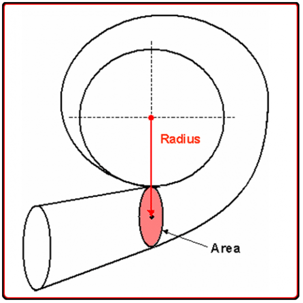
The A/R parameter has different effects on the compressor and turbine performance, as outlined below.
Compressor A/R - Compressor performance is comparatively insensitive to changes in A/R. Larger A/R housings are sometimes used to optimize performance of low boost applications, and smaller A/R are used for high boost applications. However, as this influence of A/R on compressor performance is minor, there are not A/R options available for compressor housings.
Turbine A/R - Turbine performance is greatly affected by changing the A/R of the housing, as it is used to adjust the flow capacity of the turbine. Using a smaller A/R will increase the exhaust gas velocity into the turbine wheel. This provides increased turbine power at lower engine speeds, resulting in a quicker boost rise. However, a small A/R also causes the flow to enter the wheel more tangentially, which reduces the ultimate flow capacity of the turbine wheel. This will tend to increase exhaust backpressure and hence reduce the engine's ability to "breathe" effectively at high RPM, adversely affecting peak engine power.
Conversely, using a larger A/R will lower exhaust gas velocity, and delay boost rise. The flow in a larger A/R housing enters the wheel in a more radial fashion, increasing the wheel's effective flow capacity, resulting in lower backpressure and better power at higher engine speeds.
Compressor Surge:What is compressor surge?
The surge region, located on the left-hand side of the compressor map (known as the surge line), is an area of flow instability typically caused by compressor inducer stall. The turbo should be sized so that the engine does not operate in the surge range. When turbochargers operate in surge for long periods of time, bearing failures may occur. When referencing a compressor map, the surge line is the line bordering the islands on their far left side.
Compressor surge is when the air pressure after the compressor is actually higher than what the compressor itself can physically maintain. This condition causes the airflow in the compressor wheel to back up, build pressure, and sometimes stall. In cases of extreme surge, the thrust bearings of the turbo can be destroyed, and will sometimes even lead to mechanical failure of the compressor wheel itself.
Common conditions that result in compressor surge on turbocharger gasoline engines are:
* A compressor bypass valve is not integrated into the intake plumbing between the compressor outlet and throttle body
* The outlet plumbing for the bypass valve is too small or restrictive
* The turbo is too big for the application
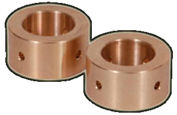
Bearing TypesJournal Bearings vs. Ball Bearings
The journal bearing has long been the brawn of the turbocharger, however a ball-bearing cartridge is now an affordable technology advancement that provides significant performance improvements to the turbocharger.
The cartridge is a single sleeve system that contains a set of angular contact ball bearings on either end, whereas the traditional bearing system contains a set of journal bearings and a thrust bearing
Journal Bearings
Ball Bearings

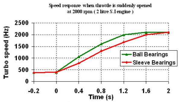
Turbo Response ? When driving a vehicle with the cartridge ball bearing turbocharger, you will find exceptionally crisp and strong throttle response. Ball Bearing turbochargers spool up ~15% faster than traditional journal bearings. This produces an improved response that can be converted to quicker 0-60 mph speed.
Tests run on CART turbos have shown that ball-bearings have up to half of the power consumption of traditional bearings. The result is faster time to boost which translates into better drivability and acceleration.
Reduced Oil Flow ? The ball bearing design reduces the required amount of oil required to provide adequate lubrication. This lower oil volume reduces the chance for seal leakage. Also, the ball bearing is more tolerant of marginal lube conditions, and diminishes the possibility of turbocharger failure on engine shut down.
Improved Rotordynamics and Durability ? The ball bearing cartridge gives better damping and control over shaft motion, allowing enhanced reliability for both everyday and extreme driving conditions. In addition, the opposed angular contact bearing cartridge eliminates the need for the thrust bearing commonly a weak link in the turbo bearing system.
Other Ball Bearing Options ? Another option one will find is a hybrid ball bearing. This consists of replacing only the compressor side journal bearing with a single angular contact ball bearing. Since the single bearing can only take thrust in one direction, a thrust bearing is still necessary and drag in the turbine side journal bearing is unchanged.
